Nearing it's centennial, KMOX-AM (1120 kHz) is a 50,000-watt clear-channel AM radio station with studios located in downtown St. Louis, MO, USA.
But their broadcast tower is located about 10 miles northeast, in Pontoon Beach, IL. My Dad was the director of engineering overseeing the tower and studios for about 20 years, and though he's no longer there, he and I got permission from Audacy and the St. Louis engineers (thanks!) to tour the site, and learn a bit about how they broadcast their AM signal—which reaches all the way into Canada and Mexico at night!
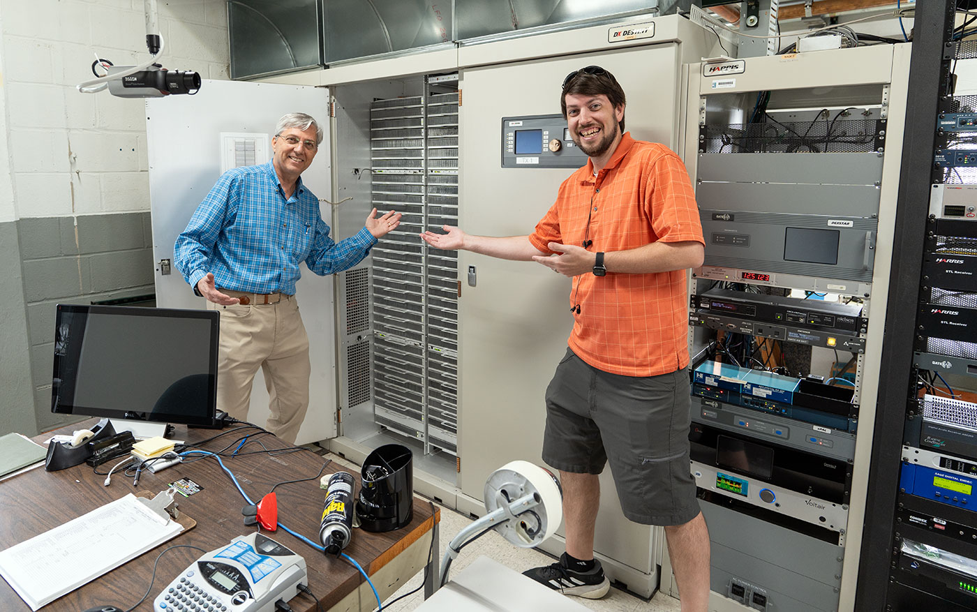
In this blog post, I'll write a bit about KMOX's tower system (AM towers are a lot different than FM, like the FM Supertower we toured last year), the transmitter, and the some of the history found at that tower site.
We posted a comprehensive video on the tower site tour on YouTube—you can view it here:
Seriously, go check out the video. There are few times when I'd recommend you watch a video instead of read a blog post, but this is one of them.
50 kW Tower System
One of the first tasks my Dad (Joe Geerling) took on when he became the director of engineering for CBS's St. Louis-area stations (Audacy neé Entercom neé CBS Radio) was the rebuilding of its main transmission tower.
The old tower was built decades ago and no matter how well you coat metal, when it's in the midwest freeze-thaw-severe-weather-freeze cycle, it's not going to last centuries! Certainly not when you're constantly pumping 50,000 watts of RF into it 24x7.
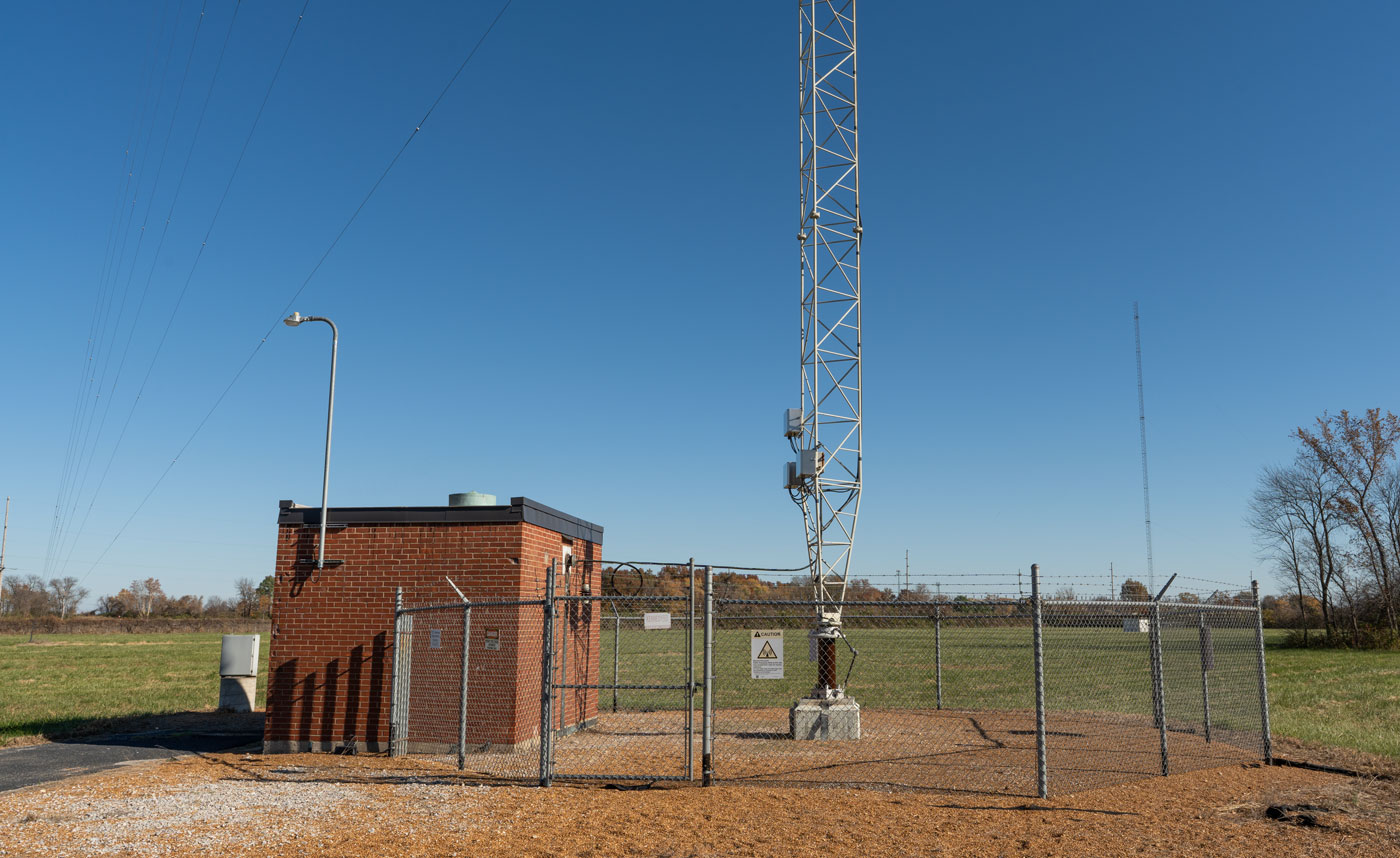
There are a few interesting differences between AM towers and FM towers—for FM frequencies, the antenna is typically installed in small-ish antenna bays as far up a mast as possible. There's a cable that routes up the tower to that antenna system, and it radiates energy by line of sight to all the receivers.
For AM, the tower is the antenna! The entire metal structure radiates the AM radio wave. And that presents some challenges:
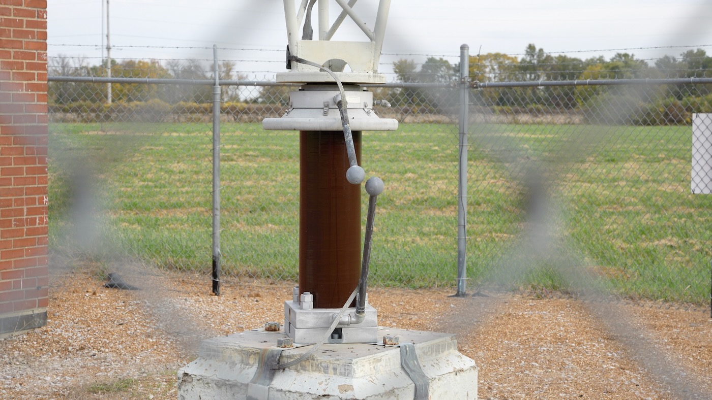
That brownish thing at the bottom is a porcelain insulator (filled with some oil), and it completely isolates the tower (antenna) from ground. Those weird balls on sticks are for lightning protection. Their goal is to direct lightning energy directly into ground. But if the balls are spaced too closely, they'll just short the tower to ground, and that's not great. Too far apart, and they're useless for lightning protection.
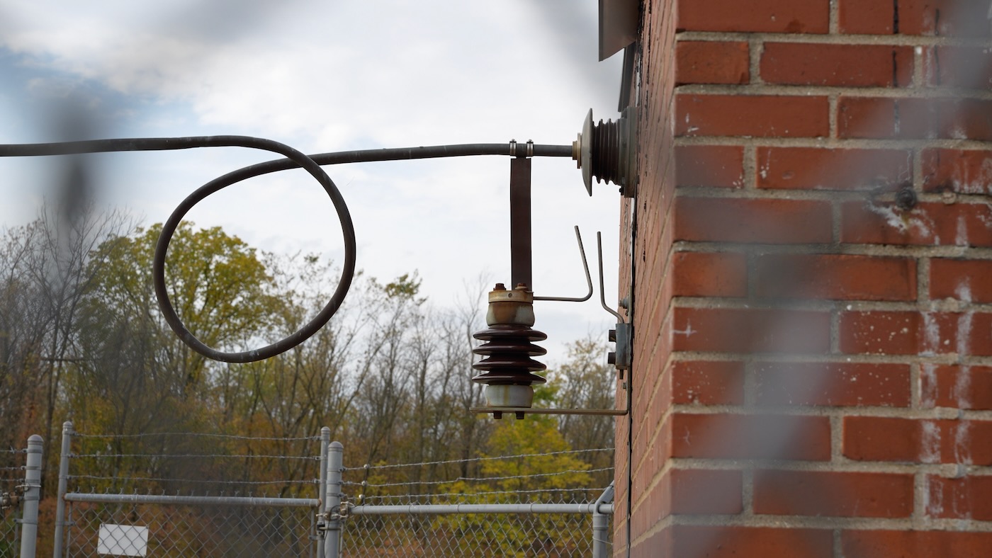
There is also additional protection in various other places, to isolate all the ground paths for the tower, like this additional gap between the feed line output from the ATU (Antenna Tuning Unit, the brick building) and the copper feed line:
Not pictured in this post (but identified in the video), there is also a ground plane for the antenna. There's a copper mesh buried just under the rock in these photos, and around the edge of that copper mesh is a thick ground strap. Attached to that are hundreds of 'radials', long copper lines that go out into the field around the tower. All AM antennas need this grounding system to propagate their signal correctly.
But... when you're radiating 50,000 watts in all directions (this tower is a single-tower system, many AM stations use multiple towers with phase shifting to direct their signal more precisely), there's no getting around every metal object absorbing some of that energy.
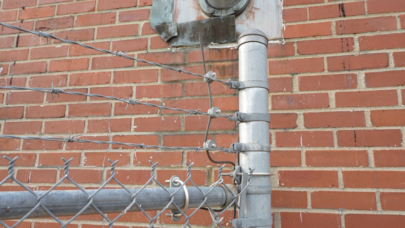
So to (a) provide safety for workers who need to get near the tower and (b) try to make metal objects invisible to the RF signal, everything is well-grounded. From the ATU, and other small buildings around the site, to even the barbed wire running along the top of the fence.
Anything that's not grounded will absorb or reflect a lot of energy... and that can lead to catastrophic failure, as we'll get to later :)
The eagle-eyed reader will note this tower has guy wires—it is a single thin mast going up that is lashed to the earth with long metal wires.
How do you ensure the RF doesn't go down the guy wires, then? You have to insulate them, too:
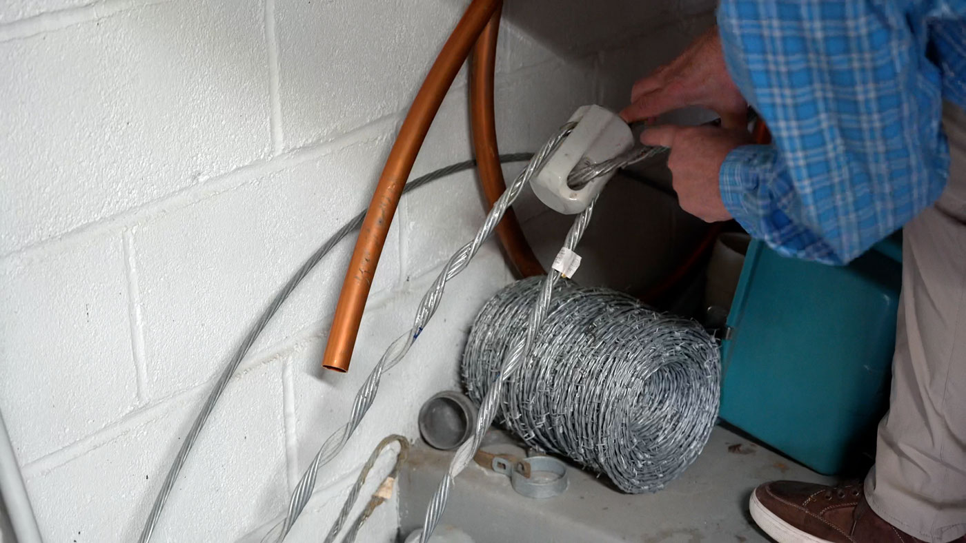
There are also long insulated connections at the tower that connect the wires to the tower as well. And you might also wonder, if you've ever seen an AM tower at night—how do you light up safety lights (to warn off airplanes) on a tower that would fry anything it touches? We'll get to that soon, after I mention something inside the little building at the base of the tower.
ATU (Antenna Tuning Unit) aka The Doghouse
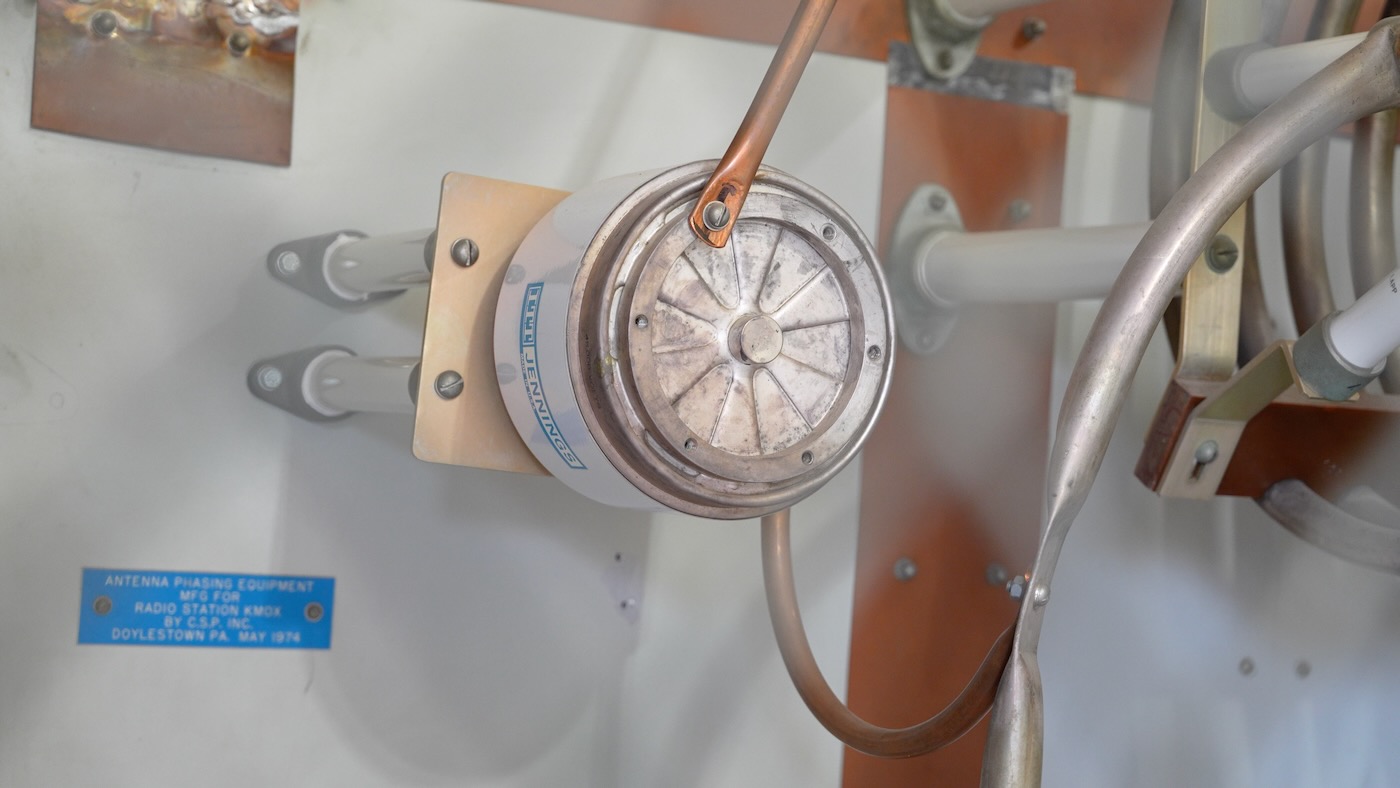
Inside that building are some of the scariest capacitors:
And inductors:
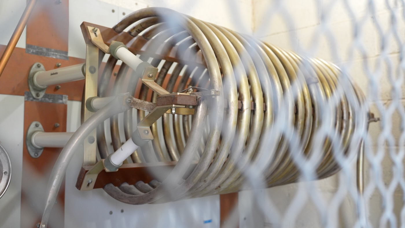
...that I've ever seen. And when you pump all that energy through them—and they're tuned correctly—they will 'sing', and you can distinctly make out the speech that's being broadcast. The wires themselves become speakers! Watch the video at the top of the post to get a feel for how that sounds.
All the components inside the ATU are meant to tune the RF signal coming from the transmitter building—to match it to the impedance of the tower (antenna). The goal is to get as much energy to go out into the feed line and radiated through the tower, with as little as possible turning into heat, or getting reflected back (transmitters don't like reflected power!).
And I told you I'd talk more about the tower lights—before I tell you what it is, can you guess what this thing does?
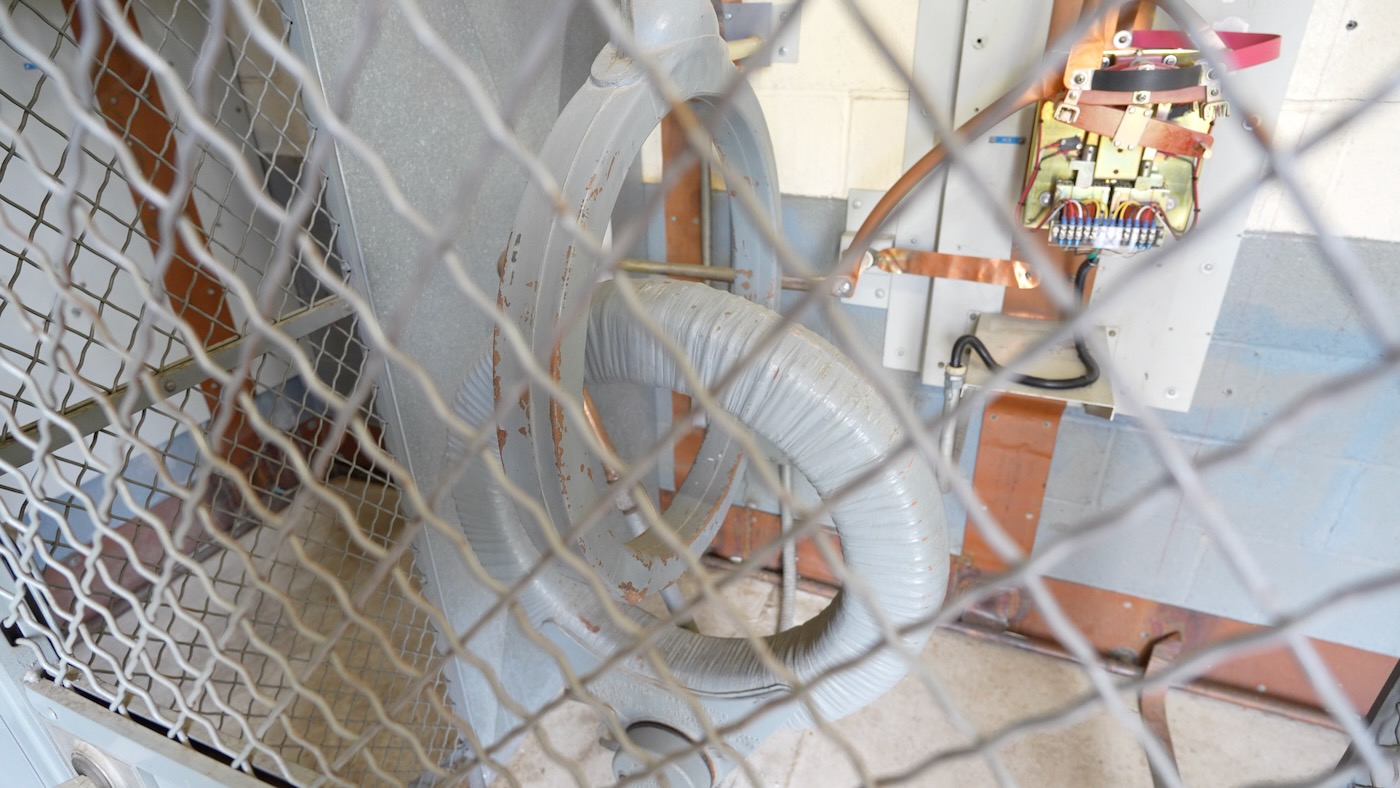
It's an Austin ring transformer, and it allows the 60 Hz AC power to pass through the inside of the RF cable going up the tower, while the 50,000 Watts of 1.120 MHz radio signal passes along the outside, and gets delivered into the tower through some copper strapping at the bottom.
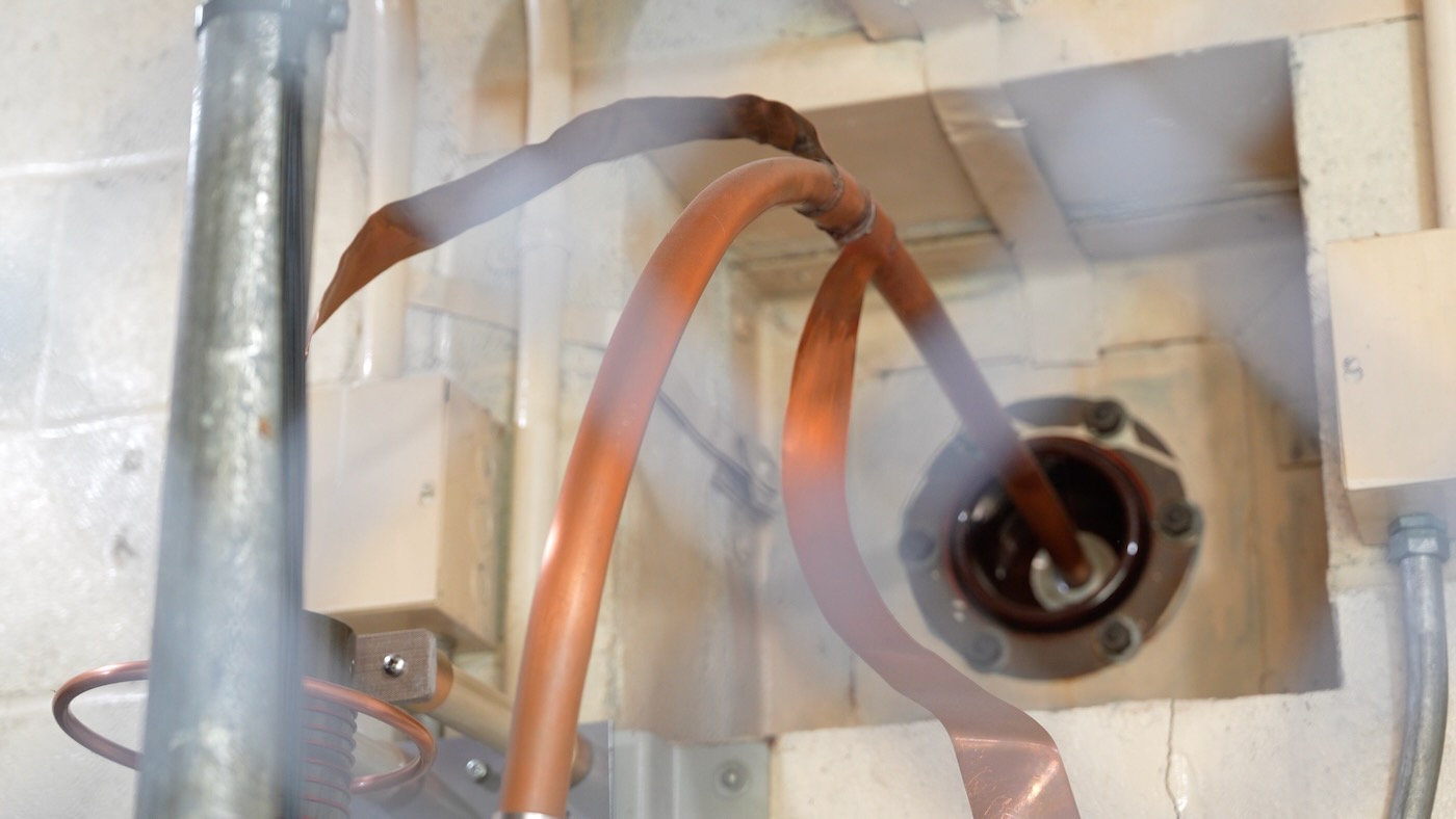
The strap you see on the left, attached to the feed line exiting the ATU, is attached to a static drain coil, which attempts to drain any static buildup on the tower due to wind. Apparently some towers have that, some don't, from what my Dad said it didn't seem like it was an absolute necessity.
But hidden inside the hollow copper tube above are some fiber optic lines. The tower lights use 60 Hz AC to flash—but how do you control the lights' flashing, or get alerted if a light isn't working?
There's a small bundle of fibers that go to the tower light control boxes, for signaling and alerting. Fiber is a lot less likely to have issues in the midst of a massive RF signal!
They also installed a spark detection system in the ATU so they'd be alerted if there was arcing due to the high currents (sometimes as time wears on, components can have tiny imperfections that lead to arcing, and left alone, that can lead to much bigger problems!).
The first version had a little wireless antenna that beamed a signal back to the transmitter building. It worked great in testing, but then 5 minutes after the tower was energized, the wireless signal went dead. When my Dad entered the ATU, he found a small black puddle permanently fused into the concrete floor under where the wireless antenna used to be.
Don't hang out in an AM tower site's ATU for an extended period of time :)
Transmitter Building and EMP-Proof PEP station
Heading back over to the transmitter building, we spotted the PEP (Primary Entry Point) facility, part of the NPWS run by FEMA. KMOX-AM is one of several stations around the country with an EMP-proof generator and tiny studio with thousands of gallons of fuel that can be used in times of major emergencies—up to and including an EMP!
FEMA has a bit more background on PEP stations, so go watch that if you want to learn more.
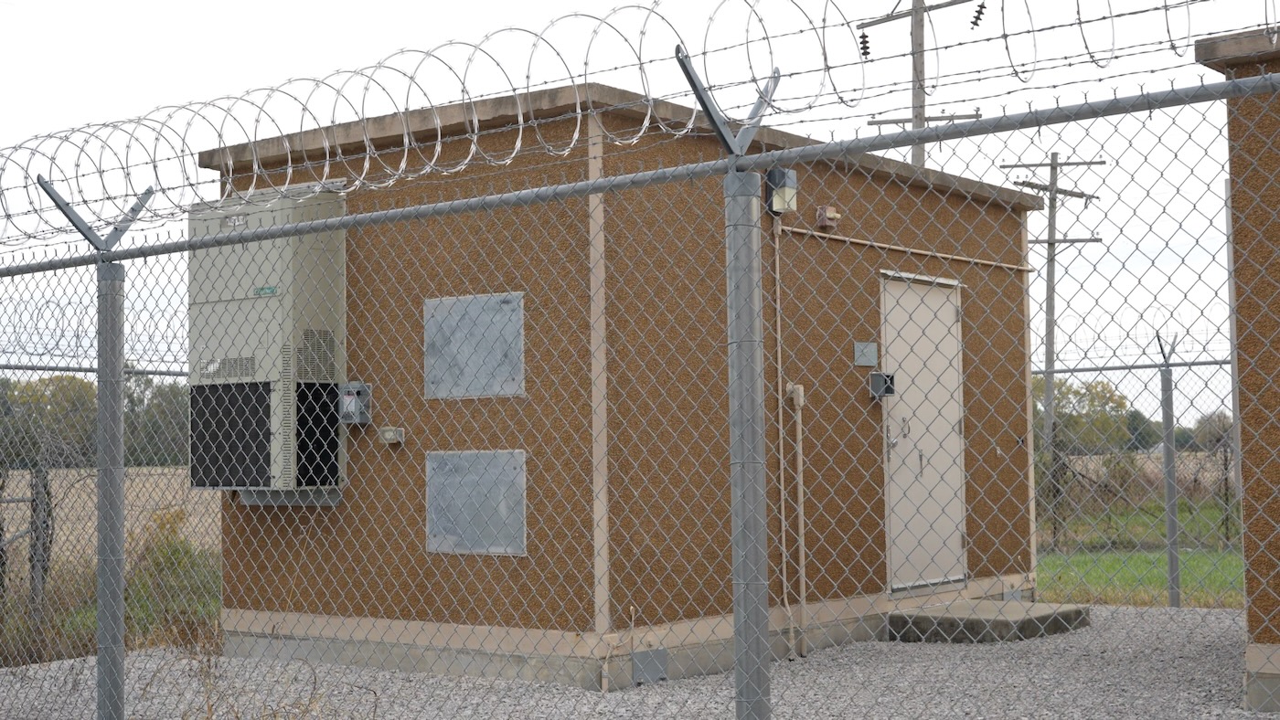
But heading inside, it's amazing how much history is preserved in the transmitter building. Being high up, and with so much redundancy (redundant power feeds, transfer switches, cooling units, transmitters, and even towers!), KMOX stores a lot of its archive material in the building. Even including the building's original blueprints!
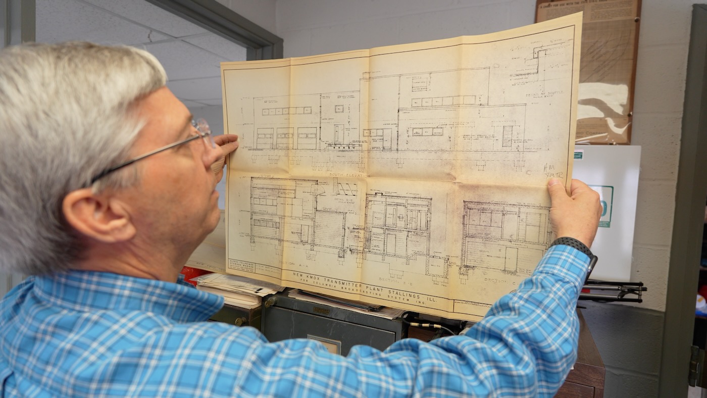
My Dad mentioned there was even copper integrated into the building's concrete exterior making it a bit of a faraday cage (though only blocking certain signals). Grounding is pretty important this close to the tower.
Speaking of power feeds, here's the main generator:
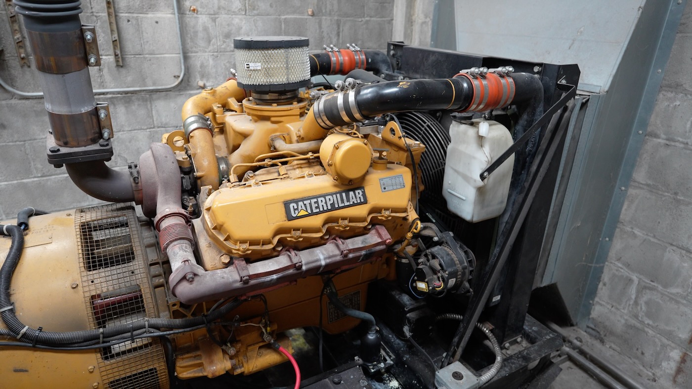
While we were there, the generator ran its weekly test; there's a secondary (and quite large) diesel tank—in addition to the 6,000 gallon tank outside—in the generator room. Alongside multiple massive transfer switches and a few 480V transformers (in a separate room nearby)!
And how do you keep all this equipment going, for decades and decades? With a well-appointed workshop, of course:
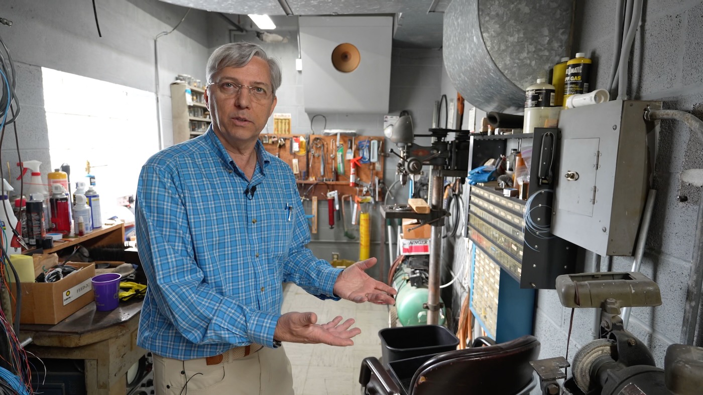
The workshop is a bit of an extravagance, from an earlier age in radio. In the 1930s, when this site was built out, there were multiple engineers working in the transmitter building around the clock, babysitting the transmitter.
Each transmitter was like a giant machine, needing care and maintenance, and the machine tools would be used to whip up improvised parts back when they weren't an Amazon warehouse-away!
And its a testament to the many engineers who worked here over the years that there's actually space on the workbench—enough that the current engineer was swapping out UPS batteries on the day we toured the facility.
Transmitter and Remote Control
We wrapped up our tour in the impressive transmitter room. KMOX has two 'twin' Harris 3DX50 transmitters (though TX2 is a little newer than TX1). Both are capable of HD Radio transmission (digital AM—it hasn't really caught on), but I believe they had HD off when we were there.
The transmitters are impressive bits of engineering, and though they are spartan in user-facing controls:
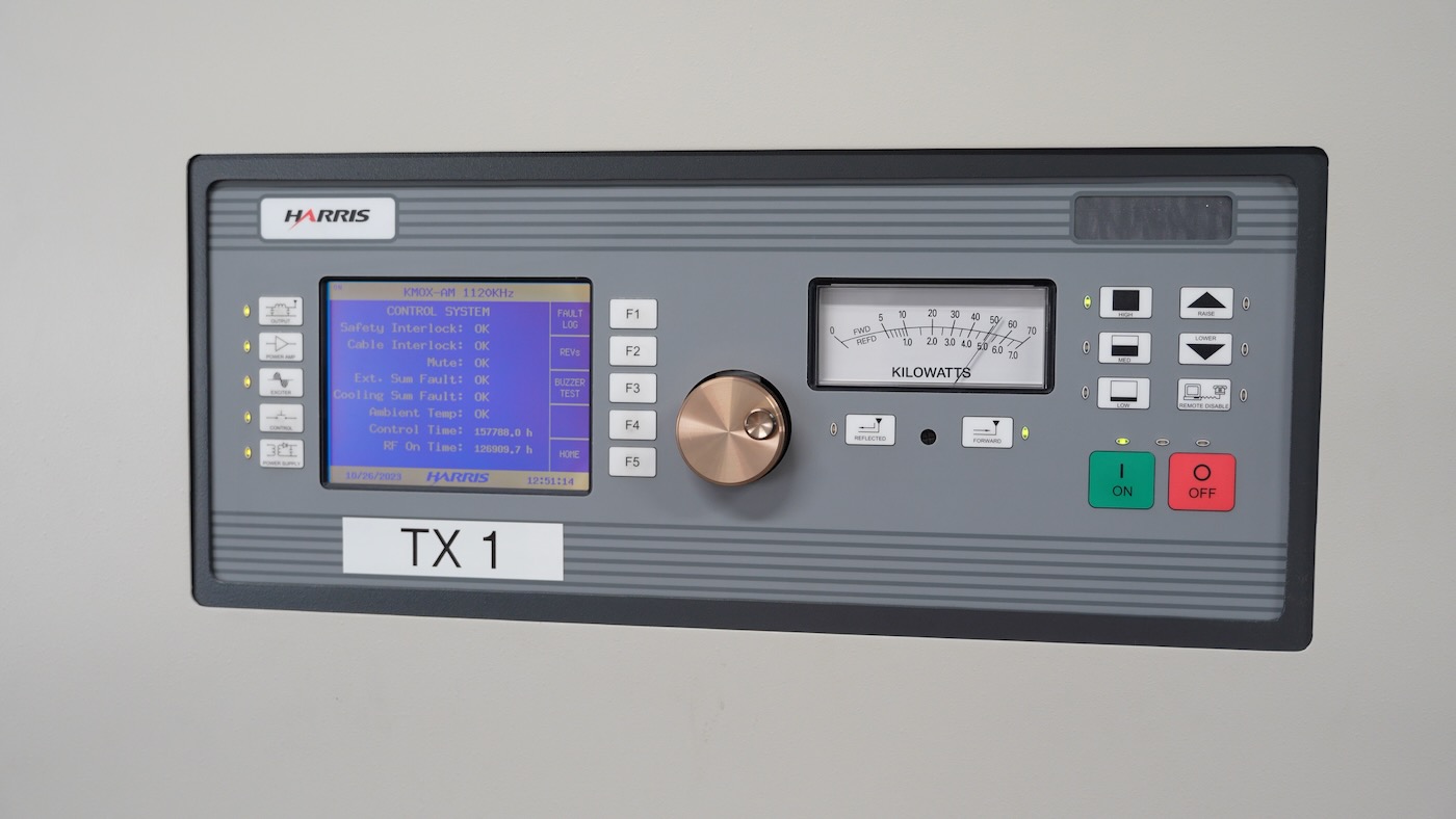
...a lot of the complexity of a modern solid state AM transmitter is hidden behind the door:
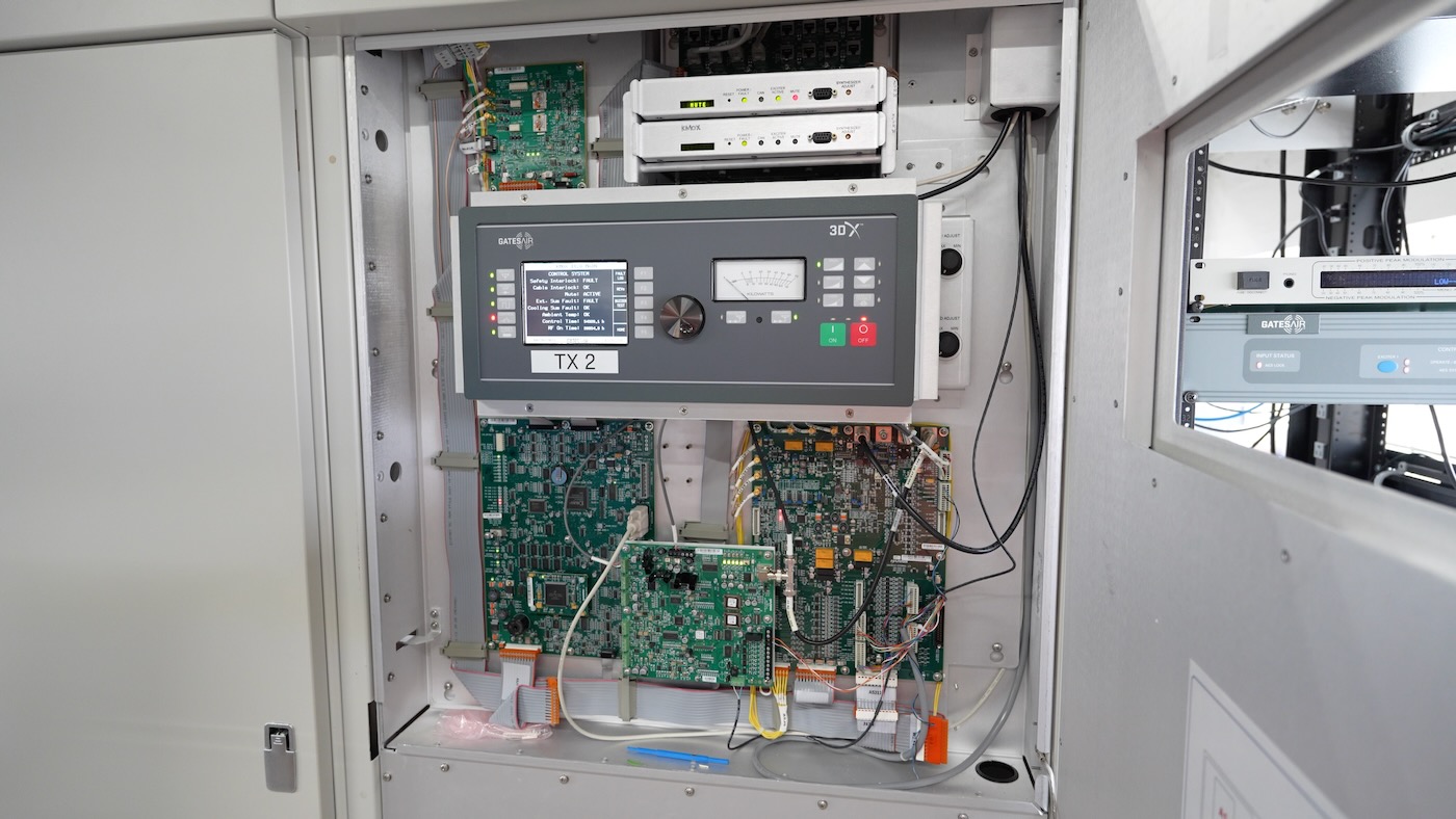
I'm amazed at how many Xilinx FPGAs I've found in broadcast gear. I'm guessing the volumes are low enough that it's not worth building a custom chip, and expensive single-quantity FPGAs like the ones here are just a tiny line item building out the massive multi-rack transmitter!
And speaking of the rest of the transmitter, it is full of these power amplifier modules, all controlled through a serial interface to pulse on and off to 'compile' a final RF waveform:
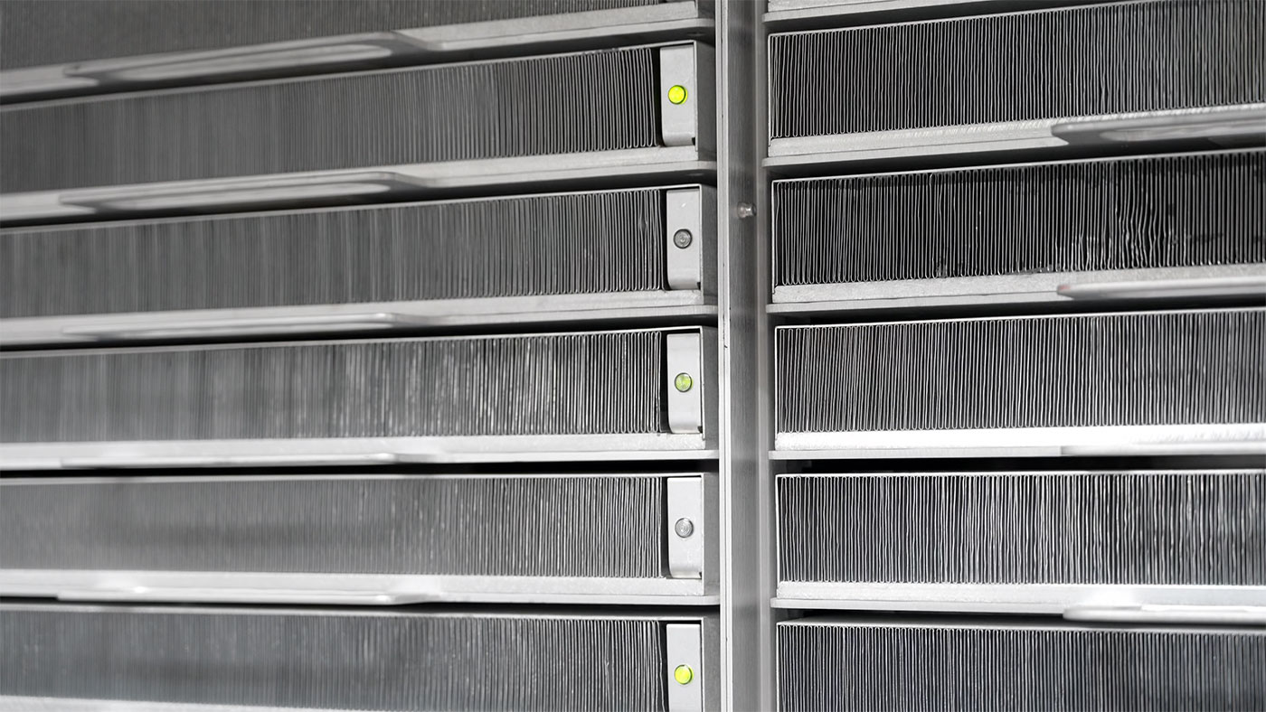
There's a lot of air constantly moving through those fins to keep everything cool. They used to have giant blowers the size of cars in the basement, cooling down massive tubes that powered the signal, but these modern transmitters have a (comparatively) small fan array in the back, pulling in cold air from the AC, and then the unit spits out hot air at the top.
Just the cooling efficiency alone means the modern transmitter room (with two 50 kW Harris transmitters and a backup 6 kW GatesAir transmitter) is less than 1/4 the size of the original transmitter + power delivery equipment footprint!
Another thing that has been radically simplified over the years is the remote control systems. For decades, engineers meticulously maintained a series of relays to switch antennas, transmitters, and towers:
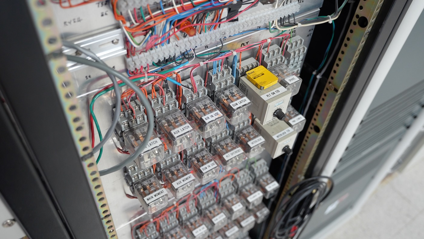
It's honestly an impressive feat keeping things so neat after so long (I know my own wiring job would look about 1000x worse than that, much less all the labeling!).
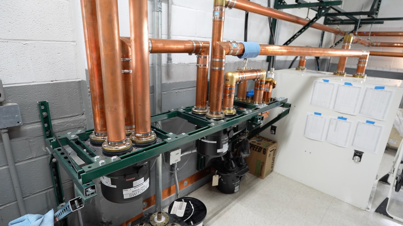
Today, the RF connections are all automated:
And there's one 3U rackmount box that takes care of all the logic:
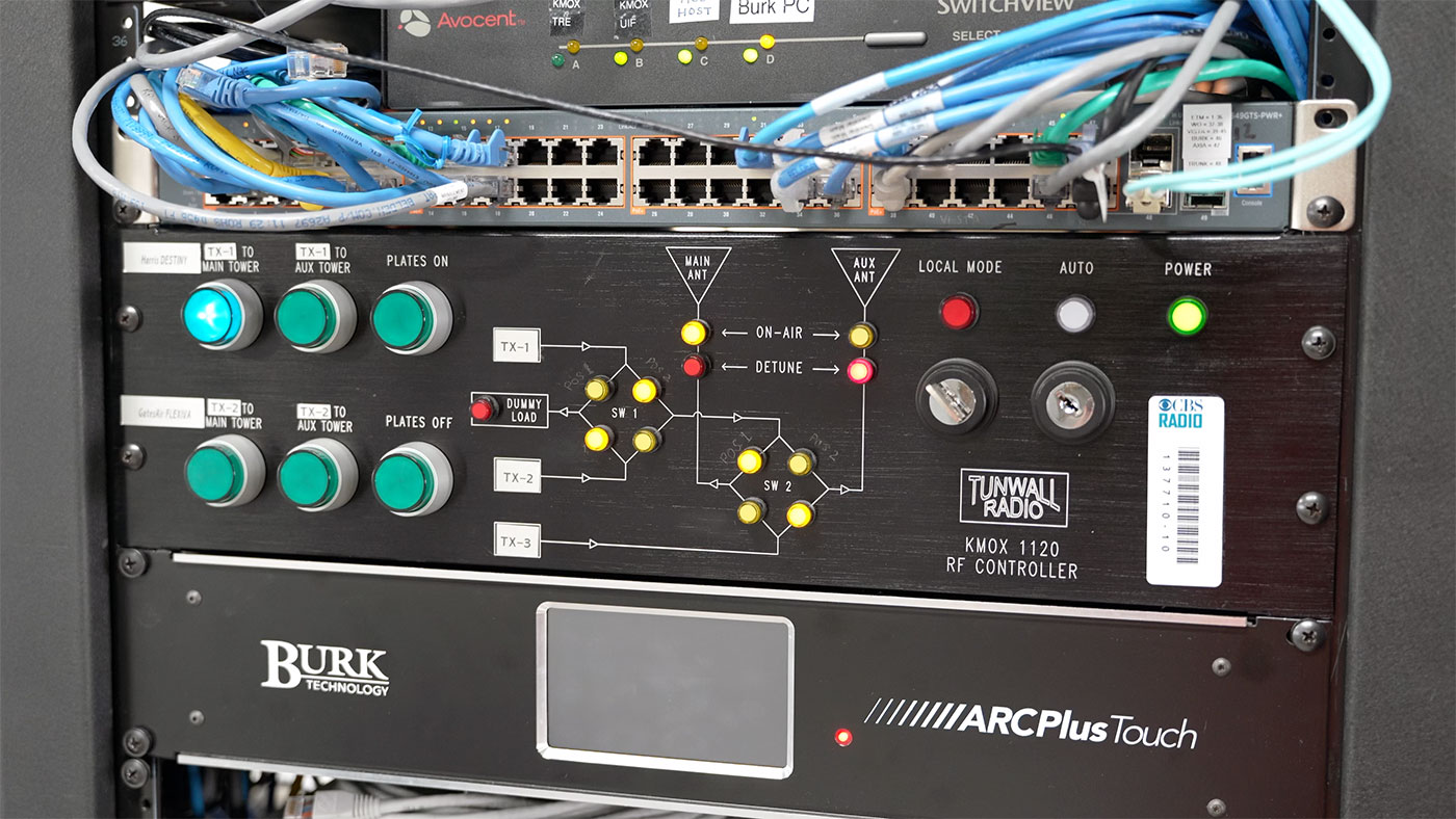
Honestly, if it weren't for the clever front panel interface that makes it easy to glance and see how it's all running, it could probably be even smaller!
AM Radio - whence forth?
Like I said earlier, if anything here piqued your interest, go watch the full video. There's really no way to convey the power of a 50 kW AM radio station with words.
If you're interested in the topic of AM radio, check out these other two Geerling Engineering videos:
Comments
Did your Dad have to hold a first or second class FCC Licsense to maintain and make adjustments to the transmitter
He does have an FCC license from way back (not sure if that's still required for most of the job of a radio engineer today—especially all the IT stuff), but he's also been a member of the SBE his whole life, it's a small but pretty active community of broadcast engineers!
Thank you for the tour of the transmitter. As a child in the 1920s/1930s in northern Indiana, my father listened to Cardinals baseball every evening. He regaled us with stories of pitchers Dizzy and Daffy Dean, and other members of the "Gashouse Gang".