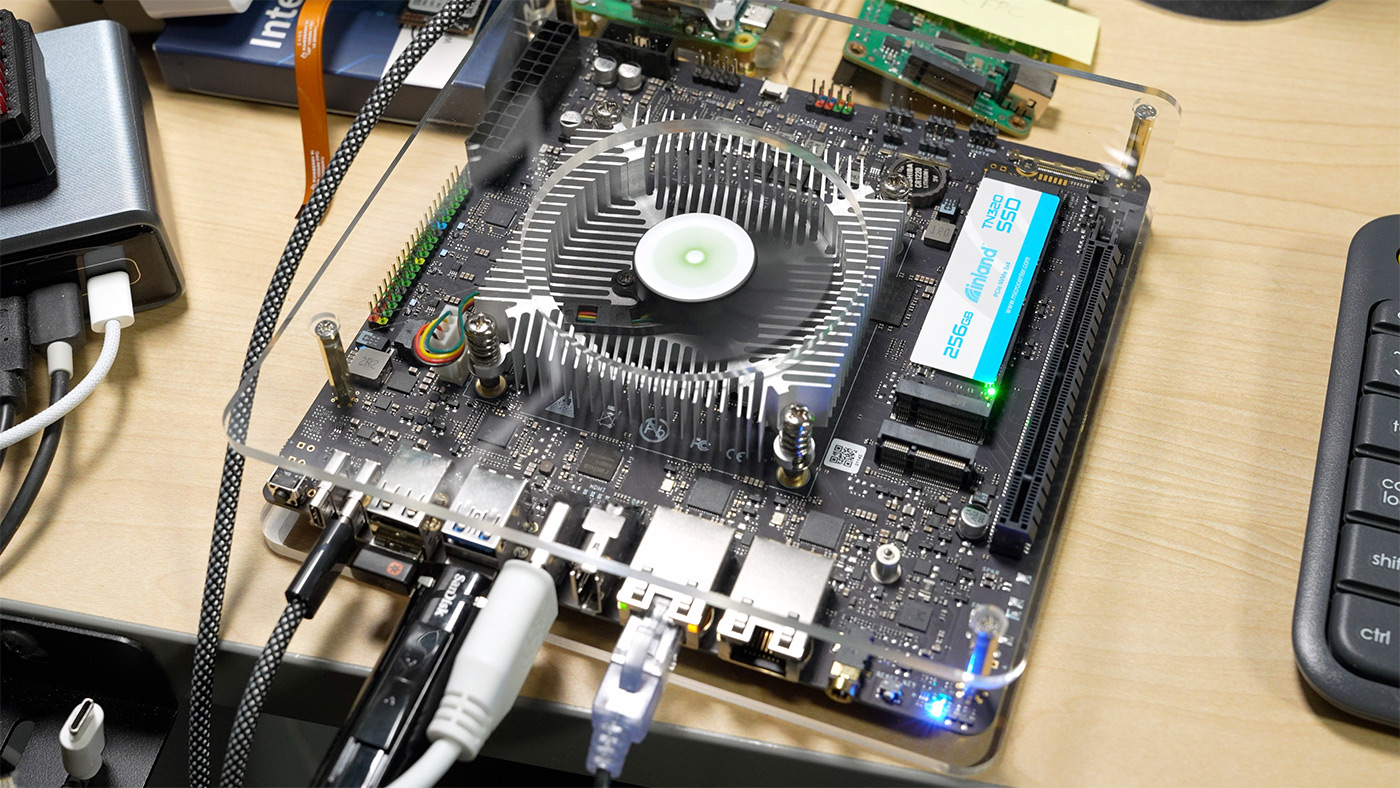
Orion O6 ITX Arm V9 board - temper your expectations

When I first heard about Radxa's Orion O6, it was being compared to Apple's M1 silicon, and the product page has extraordinary claims:

When I first heard about Radxa's Orion O6, it was being compared to Apple's M1 silicon, and the product page has extraordinary claims:
tl;dr: Use an old-fashioned USB 2.0 flash drive, format it FAT32, download the firmware, make sure it's named correctly, and use the motherboard's 'BIOS Flashback' option after powering off the computer.
This past week, I devoted far too much time to the task of updating my brand new motherboard's BIOS.
It started with a combo deal from Micro Center: a ASUS ROG Strix B650E-F Gaming WiFi motherboard, a Ryzen 9 7900x CPU, and a G.Skill Flare X5 Series 32GB DDR5-6000 memory kit, all for $599. Quite a beefy upgrade for the main PC I use to compile code and do random Linux-y tasks.

I edit videos non-stop nowadays. In a former life, I had a 2 TB backup volume and that stored my entire digital life—all my photos, family video clips, and every bit of code and text I'd ever written.
Video is a different beast, entirely.
Every minute of 4K ProRes LT footage (which is a very lightweight format, compared to RAW) is 3 GB of space. A typical video I produce has between 30-60 minutes of raw footage (which brings the total project size up to around 100-200 GB).
I've been building a Mini ITX 'quiet-ish' server using a Supermicro motherboard and some Noctua fans.
I noticed sometimes the system would start 'revving' the fans up to max power. Then after a few seconds they would get quiet again. The CPU temps and other temps on the system were stable and not worrying, but popping off the server's cover, I noticed LED8 on the motherboard would blink red every time the fans would ramp up:

That LED indicates a 'fan failure' when blinking.
Recently I built the Seaberry, a Raspberry Pi Compute Module 4 mini ITX motherboard into a PC case (video coming soon...), and got the case power button, power LED, and activity LED all wired up to the Pi:

I used the GPIO and 14-pin header present on the Seaberry (which conveniently are identical to the headers on the official CM4 IO Board), and wound up with a fully functionality power button, power LED, and activity LED!
Here's how I did it:

To get the power button working, you need to connect the case's front panel 'power switch' connector to pins 12 and 14 (GLOBAL_EN and GND), as seen in the top middle of the above picture.